The Cruiser: From Discrete Path to Continuous Motion
A Case Study in Implementing Custom Spline Interpolation.
Table of contents
Table of contents
Mission Statement
This case study explores how a path described as a sequence of 2D waypoints can be transformed into smooth, physically executable motion for a differential-drive robot.
The focus is on enforcing geometric continuity, assigning velocity and timing using basic kinematic constraints, and applying feedback control that respects non-holonomic motion.
The goal is not to optimize or replan the path, but to make an existing path description usable for stable robot motion.
Scope and Assumptions
- The input is a predefined sequence of 2D waypoints.
- The path is assumed to be collision-free.
- Motion timing is used to timestamp velocity commands; execution delays result in later arrival rather than instability.
- The controller operates on geometric error and does not enforce strict time synchronization.
- Obstacle avoidance, global planning, and torque-level control are outside the scope of this work.
Breakdown: From Theory to Implementation
This breakdown is designed to take you from the mathematical theory prototyping to the engineering implementation:
The Smoothing Technique: Catmull–Rom Splines
Catmull–Rom splines are chosen because:
- The curve interpolates the original waypoints
- First-order continuity (\(C^1\)) is guaranteed
- Tangent vectors are determined locally from neighboring points
Key Concept: The core of the method is solving for the polynomial coefficients \([a, b, c, d]\) that satisfy the position and tangency constraints.
Boundary and Interpolation Conditions
Each spline segment is mathematically defined by four consecutive control points \((P_0, P_1, P_2, P_3)\). The resulting cubic polynomial is parameterized over an interval \(t \in [0, 1]\), which maps to the spatial segment between the inner points \(P_1\) and \(P_2\). The outer points, \(P_0\) and \(P_3\), are used only to establish the boundary conditions for the tangents.
Specifically, the tangent at \(P_1\) is derived from the vector spanning from \(P_0\) (the “past” point) to \(P_2\) (the “future” point), scaled by half. Similarly, the tangent at \(P_2\) is derived from the vector spanning from \(P_1\) to \(P_3\). These “past-to-future” vectors effectively determine the direction and magnitude of the curve’s entry and exit at each interpolated waypoint.
To handle the start and end of the overall path, the waypoint list is padded by duplicating the first and last points.
The curve segment \(P(t)\) for \(t \in [0, 1]\) is constructed to satisfy the following formal constraints:
- Position Conditions: The curve must pass through the inner points.
- \(P(0) = P_1\) (The curve starts at the second control point)
- \(P(1) = P_2\) (The curve ends at the third control point)
- Tangent Conditions: The tangents are defined using a “centered-difference” approach.
- \(P'(0) = \frac{1}{2}(P_2 - P_0)\) (The tangent at the start point \(P_1\) is defined by the vector from its “past” point \(P_0\) to its “future” point \(P_2\)).
- \(P'(1) = \frac{1}{2}(P_3 - P_1)\) (Similarly, the tangent at the end point \(P_2\) is defined by the vector from its “past” point \(P_1\) to its “future” point \(P_3\)).
These boundary conditions are what force the curve to pass through the original waypoints while maintaining continuous velocity across segments.
While these conditions can be used to solve for the coefficients of the polynomial \(P(t) = a t^3 + b t^2 + c t + d\), the prototype implements this more efficiently using the equivalent matrix form:
\[P(t) = \begin{bmatrix} 1 & t & t^2 & t^3 \end{bmatrix} \begin{bmatrix} 0 & 1 & 0 & 0 \\ -0.5 & 0 & 0.5 & 0 \\ 1 & -2.5 & 2 & -0.5 \\ -0.5 & 1.5 & -1.5 & 0.5 \end{bmatrix} \begin{bmatrix} P_0 \\ P_1 \\ P_2 \\ P_3 \end{bmatrix}\]Depictions:
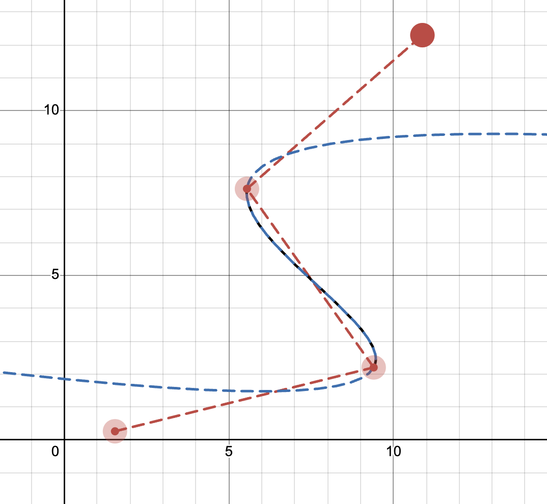 A single segment is defined by 4 control points, but only spans the inner two. | 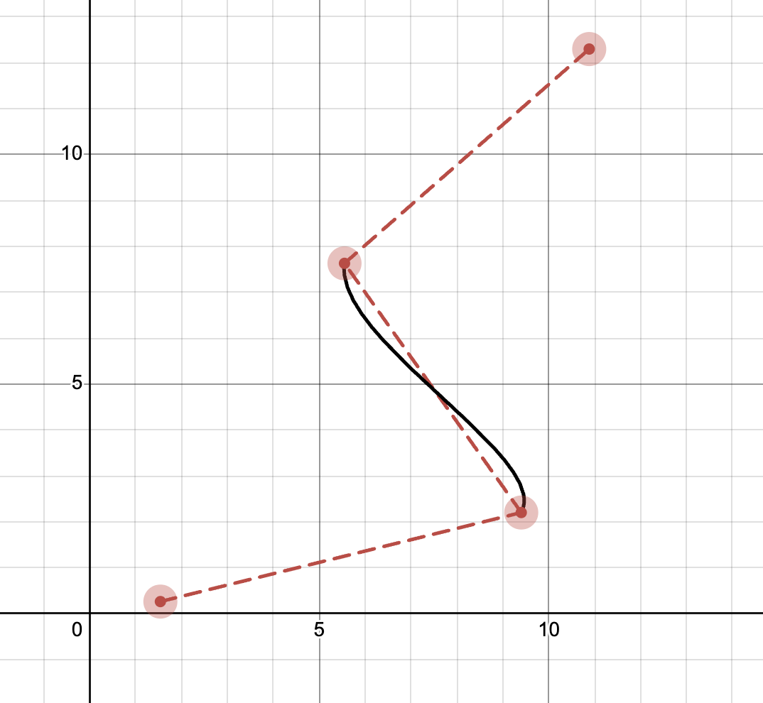 The full path is constructed by chaining these segments together. |
A few common test cases ensuring the smoothing works as expected:
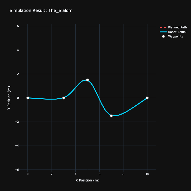 The Slalom | 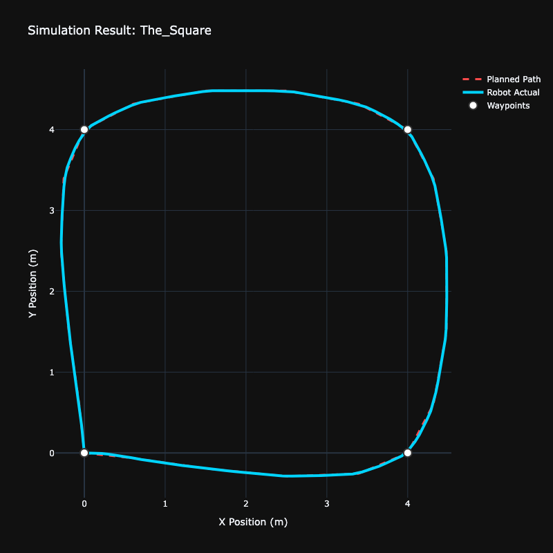 The Square Path | 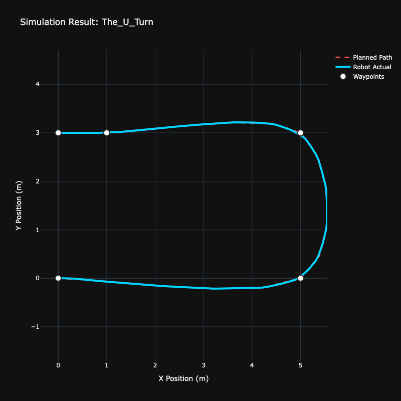 The U-Turn |
The Physics: Kinematic Constraints
A smooth curve is useless if it demands infinite acceleration. We implement a Dual-Pass Velocity Profiler (Forward/Backward) to ensure the robot respects its physical limits (\(v_{max}, a_{max}\)) and stops precisely at the goal.
First pass:
Starting from the first point with zero velocity, we iterate forward through the path. For each segment of length \(s\), we calculate the maximum possible velocity at the end of the segment using the time-independent kinematic equation: \(v_{next} = \sqrt{v_{prev}^2 + 2 a_{max} s}\) This velocity is then clamped by the robot’s absolute maximum velocity, \(v_{max}\). This pass ensures the robot never exceeds its acceleration or velocity limits while speeding up.
However, this pass alone doesn’t guarantee the robot can stop at the final destination. It might arrive at the goal going at full speed.
Second pass:
To solve the stopping problem, we run the same algorithm again, but this time in reverse. We start at the final waypoint with a velocity of zero and work backward to the start. This generates a velocity profile that ensures the robot can decelerate appropriately to a complete stop at the goal.
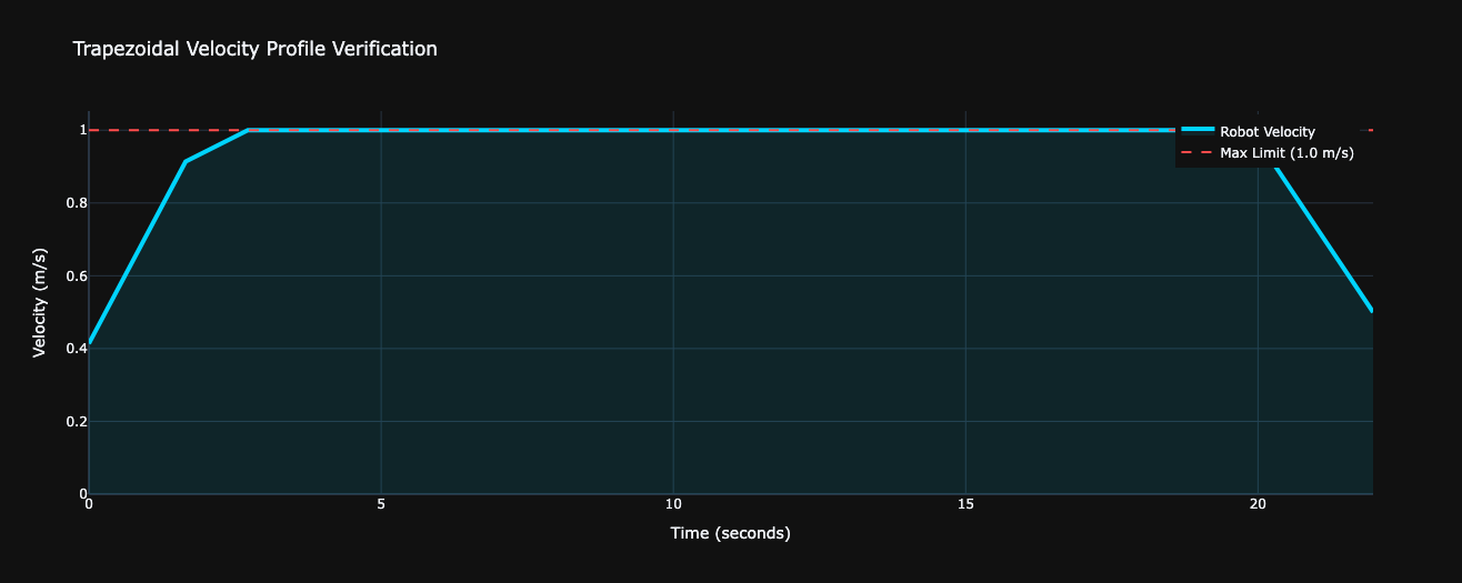
Merging:
Finally, for each point along the path, we take the minimum of the velocities calculated in the forward and backward passes. This combined profile respects both acceleration constraints when speeding up and deceleration constraints when slowing down, resulting in a smooth, executable trapezoidal velocity profile.
Timestamping the Velocity
We now need to timestamp the velocity, to create a estimated trajecory that can be used by controllers.
With a velocity assigned to each point, we can now calculate the time it takes to travel between them. The prototype calculates the time delta (\(\Delta t\)) for each segment of length \(s\) by assuming constant acceleration and using the average velocity:
\[\Delta t = \frac{s}{v_{avg}} = \frac{s}{\frac{v_{start} + v_{end}}{2}}\]By accumulating these time deltas, we can assign a timestamp to every point in the path, transforming our smoothed path into a time-parameterized trajectory.
The Control: Proportional Controller
A time-stamped trajectory is a plan, but a robot needs a controller to execute it. We implement a simple geometric proportional (P) controller to generate linear (\(v\)) and angular (\(\omega\)) velocity commands based on the robot’s pose error.
For a given current_pose (\(x_r, y_r, \theta_r\)) and target_point (\(x_t, y_t\)), the controller calculates:
- Distance Error: \(e_{dist} = \sqrt{(x_t - x_r)^2 + (y_t - y_r)^2}\)
- Angle Error: \(e_{\theta} = \text{atan2}(y_t - y_r, x_t - x_r) - \theta_r\)
The control logic has two critical features:
-
Angle Normalization: The raw angle error can be outside the range \([-\pi, \pi]\). To ensure the robot always takes the shortest turn, we normalize it using the modulo operator, as seen in the prototype:
\[e_{\theta, norm} = (e_{\theta} + \pi) \pmod{2\pi} - \pi\] -
Coupled Linear and Angular Control: A key feature of this controller is how it couples linear velocity to orientation error. The forward velocity command is scaled by the cosine of the angle error:
\[v_{cmd} = k_{p,lin} \cdot e_{dist} \cdot \cos(e_{\theta, norm})\]
This has an intuitive effect:
-
If the robot points directly at the target (\(e_{\theta, norm} \approx 0\)), then \(\cos(e_{\theta, norm}) \approx 1\), and it moves forward at a speed proportional to its distance.
-
If the robot is pointing away from the target (\(e_{\theta, norm} \approx \pm \pi/2\)), then \(\cos(e_{\theta, norm}) \approx 0\), and the robot stops moving forward to prioritize turning and correcting its orientation first.
The angular velocity command is a simple proportional term on the normalized angle error:
\[\omega_{cmd} = k_{p,ang} \cdot e_{\theta, norm}\]This controller is a Proportional (P) controller and is purely geometric. It calculates commands based only on the robot’s current spatial error (distance and angle) relative to a target point. As implemented in the prototype, it intentionally ignores the timestamp of the target point.
The timestamps are generated to create a complete trajectory, which is essential for more advanced, time-aware controllers (like a full PID controller). For instance, the Integral (I) and Derivative (D) components would use the time information to correct for errors that accumulate over time or change rapidly. This P-controller serves as the foundational first step.
Note on the Prototype Code: The following Python snippet is a conceptual prototype. For production use, it would require more robust error handling, integration with a proper state machine, and thorough testing. The code has been enhanced to include a basic goal tolerance check, which is a critical feature for preventing oscillations near the target.
import numpy as np
from math import atan2, sqrt, cos, sin, pi
from dataclasses import dataclass
from abc import ABC, abstractmethod

@dataclass
class ControllerConfig:
    """Configuration for the ProportionalController."""
    k_p_lin: float = 0.8
    k_p_ang: float = 4.0
    max_v: float = 1.2
    max_w: float = 3.0
    goal_tolerance: float = 0.05  # Stop within 5 cm of the target

class ControllerInterface(ABC):
    """
    Defines a contract for a controller. This aligns with the plugin-based architecture
    used in robotics frameworks like Nav2, which is built on ROS 2. This interface
    serves as a conceptual model for creating swappable control algorithms.
    """
    @abstractmethod
    def compute_command(self, current_pose, target_point):
        """Computes velocity commands to drive the robot towards a target point."""
        pass

class ProportionalController(ControllerInterface):
    def __init__(self, config: ControllerConfig):
        self.config = config

    def compute_command(self, current_pose: tuple, target_point: tuple) -> tuple:
        rx, ry, r_theta = current_pose
        _, tx, ty = target_point

        dx = tx - rx
        dy = ty - ry
        dist_error = sqrt(dx**2 + dy**2)

        # If we are within the goal tolerance, command zero velocity.
        if dist_error < self.config.goal_tolerance:
            return 0.0, 0.0

        desired_theta = atan2(dy, dx)
        angle_error = desired_theta - r_theta

        # Normalize the angle to ensure the shortest turn is taken.
        angle_error = (angle_error + pi) % (2 * pi) - pi

        # Scale linear velocity by the cosine of the angle error.
        v_cmd = self.config.k_p_lin * dist_error * cos(angle_error)
        w_cmd = self.config.k_p_ang * angle_error

        # Clamp commands to the robot's physical limits.
        v_cmd = max(min(v_cmd, self.config.max_v), -self.config.max_v)
        w_cmd = max(min(w_cmd, self.config.max_w), -self.config.max_w)

        return v_cmd, w_cmd

# Example of instantiation:
# A factory would typically create this config from a file (e.g., YAML).
default_config = ControllerConfig()
controller = ProportionalController(config=default_config)
The Simulation:
The following video demonstrates the concepts in action, showing the robot smoothly tracking the generated trajectory.
Note: During the time of recording, there was an issue with convergence at the goal. As discussed in the controller section, adding a
goal_toleranceresolves this by commanding zero velocity when the robot is sufficiently close to the target.